Joy-Con Drift Repair Kit Joystick Replacement with Safe Small-Part Handling
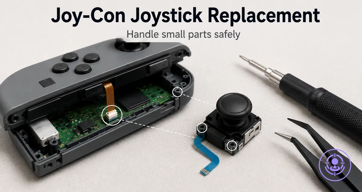
A Joy-Con drift repair kit joystick replacement involves removing the worn analog stick module and installing a new one. This task involves handling small components safely, with the main risk points being ribbon cables, tiny screws, and plastic connector latches inside the controller. Careful attention to these areas helps the installation restore normal joystick function.
This page covers the joystick-module replacement and reassembly checks only. It does not cover cleaning methods, calibration steps, or broader drift diagnosis. If the drift persists after a proper replacement, the cause may lie outside the joystick module, such as in controller calibration or battery interference. Results depend on installation quality and the condition of the controller.
Using the correct driver, applying gentle pressure, and ensuring proper alignment prevent damage to screws, ribbon cable, and latches. Success requires careful execution from opening the shell to seating the new stick module.
If drift remains after replacement, confirm that reassembly checks were completed correctly before exploring calibration or other causes.
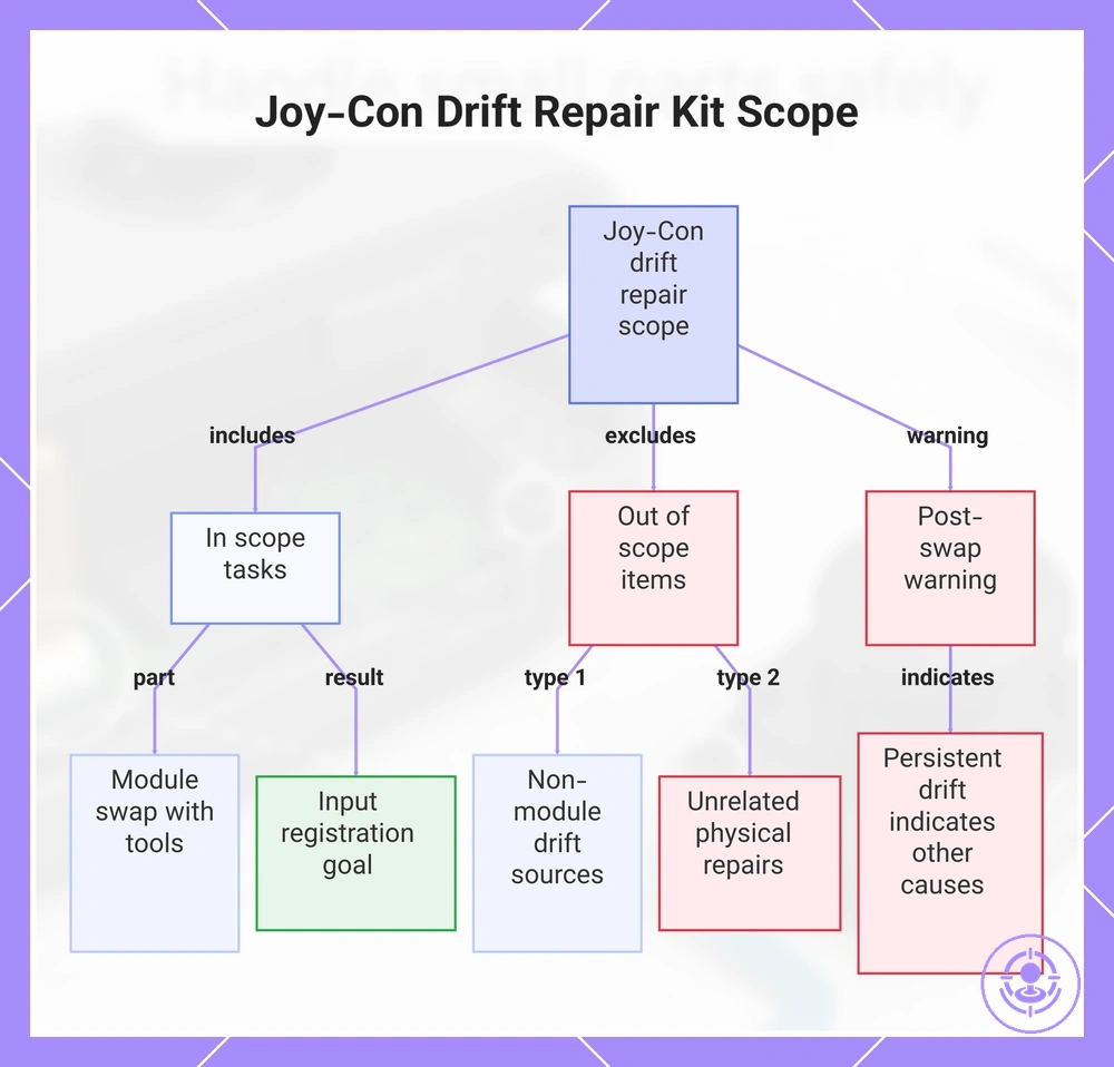
Which joystick replacement this Joy-Con drift repair kit process covers and what stays out of scope
A joystick replacement with a Joy-Con drift repair kit is swapping the joystick module on a Joy-Con controller to restore input response. The goal is that inputs register after installation. This scope covers only the module swap and the included tools.
The replacement scope depends on the joystick module task. For a broader view of the kit's contents, see the Joy-Con drift repair kit overview.
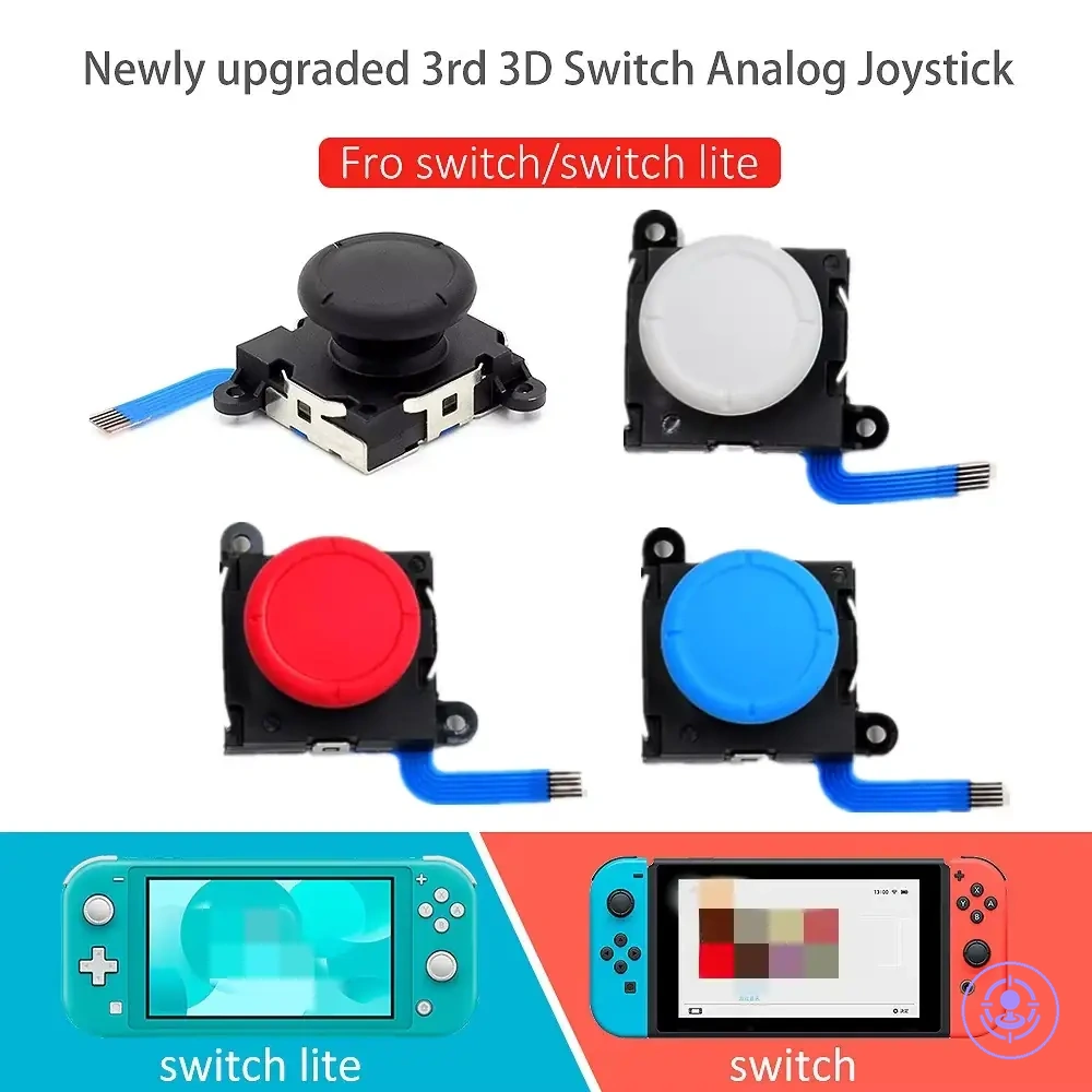
- Replacing the joystick module with the provided analog stick
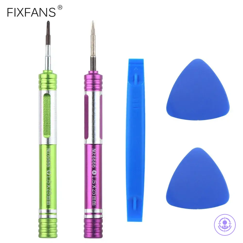
- Using included screwdrivers (Y, +) and pry tools
- Achieving input registration after correct installation
- Cleaning internal contacts or sensor surfaces
- Diagnosing drift from worn potentiometers or software
- Repairing damaged ribbon cables unrelated to the joystick
- Fixing loose battery connections or shell issues
A common assumption is that a joystick module replacement resolves all drift symptoms. However, if drift continues after the swap, the issue likely stems from other causes such as worn potentiometers. If inputs remain unresponsive or inconsistent after correct installation, do not force further module adjustments — the problem may require different troubleshooting.
This chart shows what the Joy-Con drift repair kit covers, what it excludes, and a warning about persistent drift after module replacement.
Tools, parts, and workstation setup for controlled screw and component handling
Correct tools and a stable workstation are the main safeguards against stripped screws, damaged connectors, and torn cables.
Before you begin, ensure you have the screwdrivers and screws you need for your Joy-Con model.
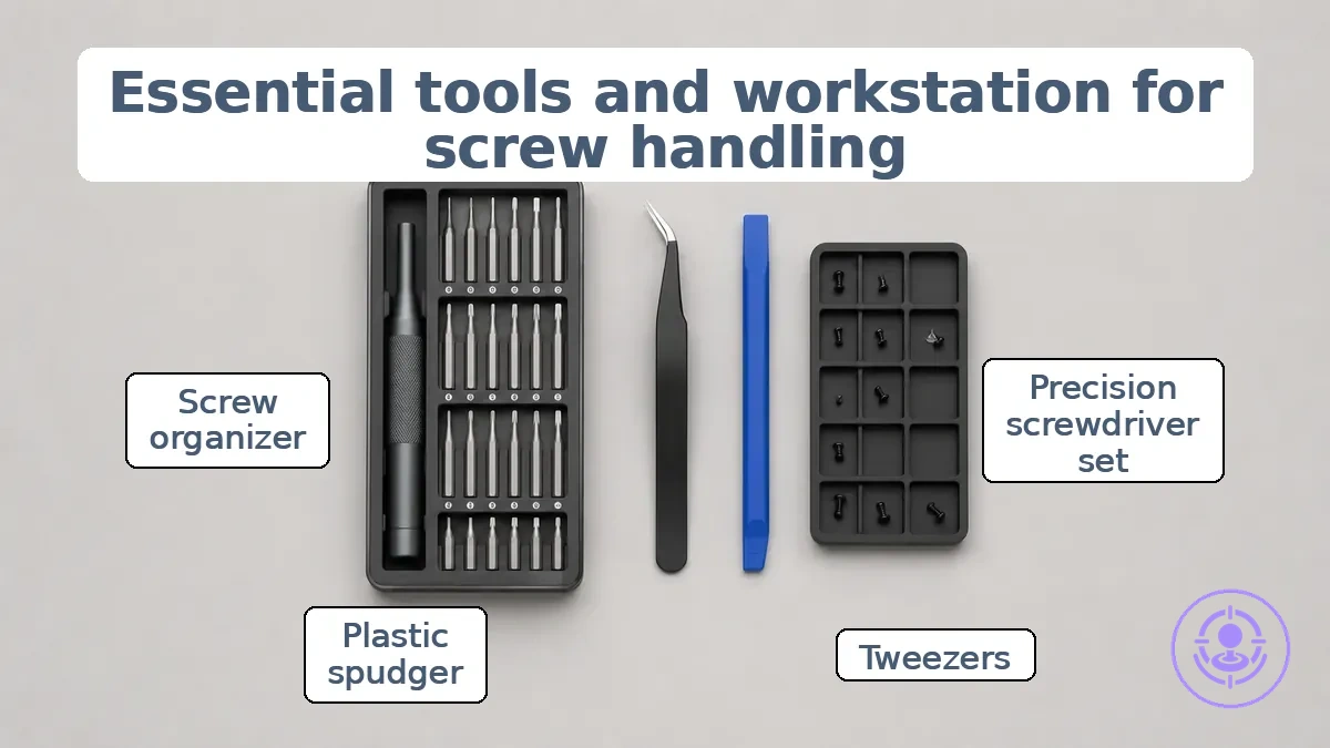
- Precision screwdriver set with the correct bit sizes for small screws.
- Tweezers for controlled handling of tiny parts and screws.
- Plastic opening tool (spudger) to reduce the risk of damaging connectors or flex cables.
- Screw tray or organizer to keep screws separated and prevent loss.
- Bright lighting to clearly see screw heads and component markings.
- Stable, clean work surface to reduce the risk of accidental movement.
- Small labeled containers for grouping screws by their original location.
Each tool or workspace feature's effectiveness depends on one attribute. For the driver, the attribute is fit — a bit that matches the screw head properly reduces the chance of stripping. For the workspace, the attribute is organization — separate trays for each screw group help prevent mixing and loss.
These choices lower the risk of component damage and support cleaner reassembly. Errors become more likely when the tool does not fit correctly or the workspace is cluttered.
When handling flex cables, avoid touching the contact pins directly because static discharge can damage sensitive components. Handle cables by their edges to reduce tearing risk.
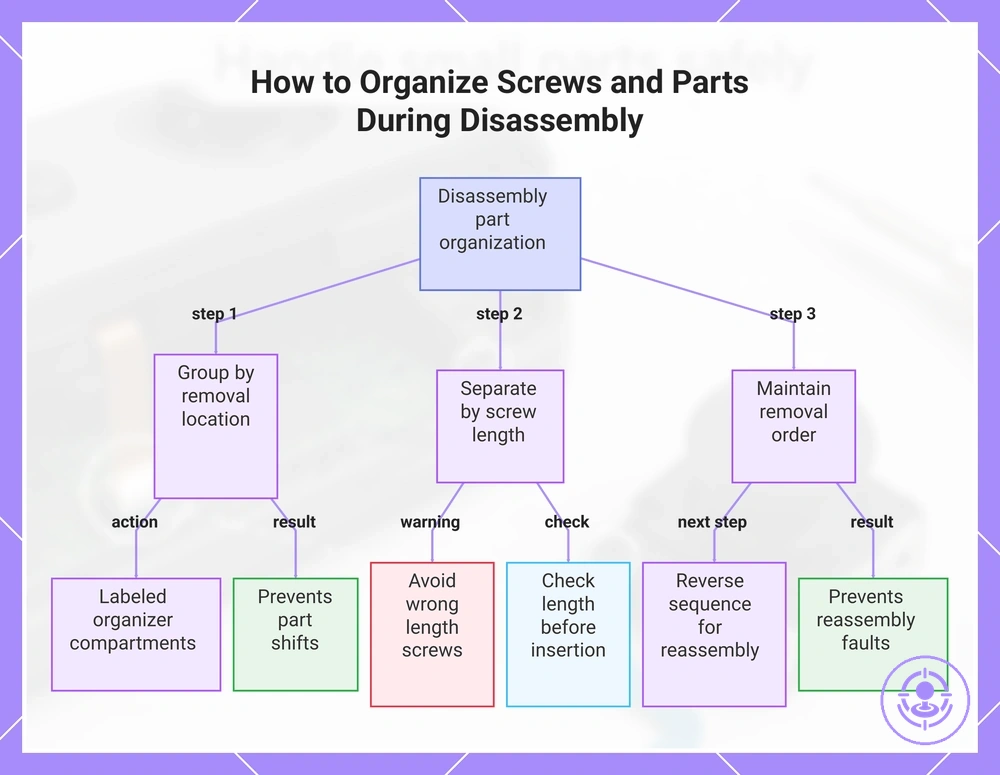
Organizing screws and keeping small internal parts from shifting during disassembly
Separating screws and small internal parts by their removal location prevents mix-ups and part shifts that cause reassembly faults. Using a screw that is too long or has the wrong thread can damage the shell or cause poor fit.
Screw length and placement can vary between device models, so a location-based system helps avoid confusion.
- Group screws and small parts by the component they came from to keep location clear.
- Separate screws by screw length to avoid using one that is too long and could damage the shell.
- Maintain removal order so reassembly follows the reverse sequence.
- Place each group in a labeled organizer with compartments to prevent accidental swapping.
- Before inserting a screw, check that its length matches the hole to ensure proper shell fit.
- Common mistake: swapping similar screws with different thread or length can cause damage.
Do not mix lengths; even a small difference can cause a misfit or bend the shell.
This chart shows the three main steps for organizing screws and small parts during disassembly to prevent reassembly faults.
Ribbon cable and connector latch handling during joystick replacement
Handling the ribbon cable and its connector latch incorrectly is a common failure point in Joy-Con joystick replacement. A torn cable or a latch that comes off can leave the joystick not responding, even if the replacement part itself is correct.
A fully seated flex cable has its contact pads aligned with the connector pins and the cable edge reaching the insertion reference line. The latch must lock to maintain that connection. Check for a straight, non-skewed cable and a latch lying flat against the connector body.
This image shows the latch in its open position and a fully seated cable.
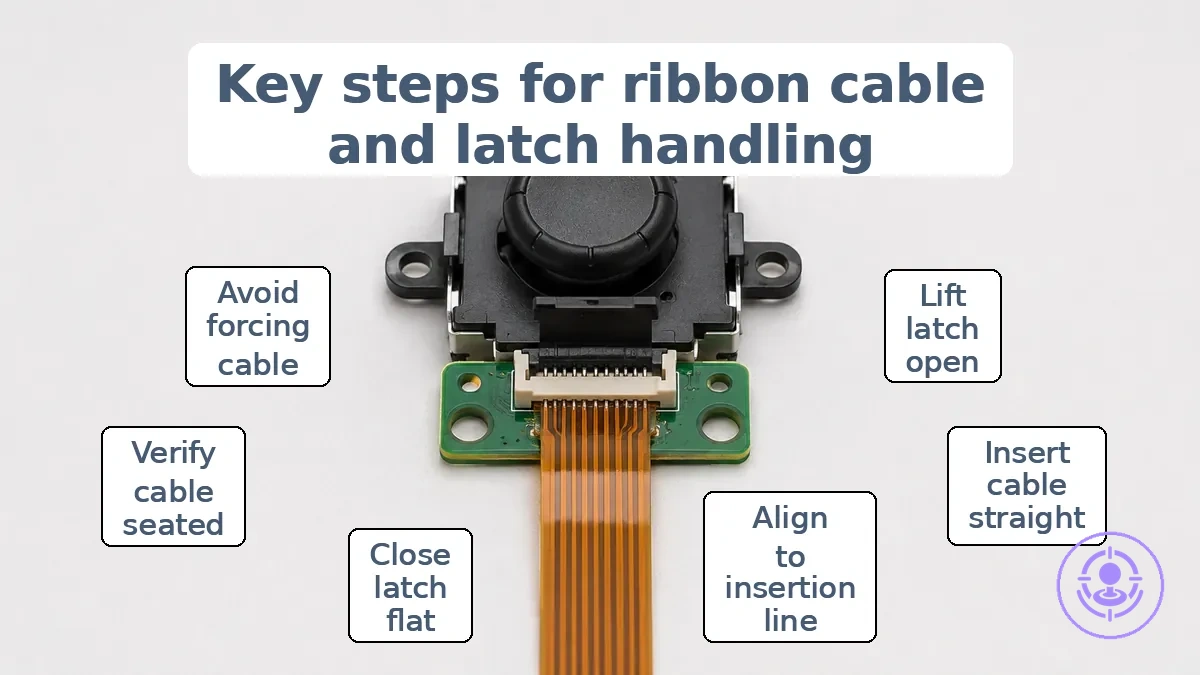
To avoid a torn cable or a joystick not responding, handle the ribbon cable and latch as follows:
- DO lift the latch fully open before inserting the flex cable.
- DO insert the cable straight, with contacts facing the correct direction.
- DO push the cable until its edge aligns with the connector's insertion line.
- DO gently close the latch until it lies flat or feels locked.
- DO verify the cable stays seated by gently tugging on it after locking.
- DON’T force the cable into a partially closed latch.
- DON’T insert the cable at an angle or skewed.
- DON’T use metal tools to push the latch or cable.
- DON’T force the cable or latch; reopen and re-seat instead.
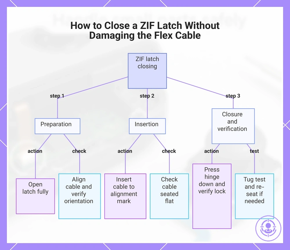
Opening and closing ZIF-style latches without tearing or creasing the flex cable
The ZIF latch hinge moves between an open position (releases pressure, allowing flex cable insertion or removal with minimal force) and a closed position (clamps the cable securely). Operating the latch with minimal force helps avoid cable damage.
To close the latch, follow these steps:
- Fully open the ZIF latch by lifting the hinge to its travel limit. Check that the latch is open before handling the cable.
- Align the flex cable with the connector opening. Verify that the contact pads face the correct direction and the cable is centered.
- Insert the cable until its alignment mark is flush with the connector edge. Check that the cable is fully seated and lies flat without twisting.
- Press the hinge down until it fully closes and locks. Check that the latch is fully closed.
- Gently tug the cable to confirm it is locked; it should not slide. If the latch won’t lock, re-seat the cable.
This chart shows the step-by-step process for safely closing a ZIF-style latch, including preparation, insertion, and verification steps.
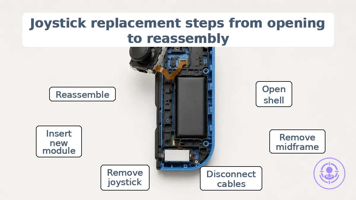
Joystick replacement steps from opening the Joy-Con to reassembly
Replacing the analog stick in a Joy-Con requires following an ordered sequence from opening the shell to reassembly, with checkpoints to verify each stage. Refer to the full step-by-step repair flow for the complete guide.
The goal of each stage is to access the joystick module without stressing fragile cables or bending connectors — starting with opening the shell and removing the midframe, then disconnecting ribbon cables to prevent tearing. Now follow the steps.
- Remove the four tri-point screws from the back panel. Check that each screw is fully clear before lifting the panel.
- Insert an opening pick into the seam at the bottom edge and slide it up the side to separate the back panel. Check that the pick does not slide too far inside to avoid damaging inner components.
- Open the Joy-Con like a book with the charging rail facing away. Check that the SL/SR cable is lightly bent under the battery compartment before clipping the halves together.
- Pry the battery connector straight up from its socket using a spudger. Check that the connector disconnects cleanly without bending the pins.
- Pry out the battery using an opening pick. Check that the battery is not deformed or punctured.
- Remove the three Phillips screws from the midframe. Check that the ZL button ribbon cable remains connected to the motherboard.
- Flip the midframe over away from the motherboard. Check that the ribbon cable is not stressed or creased.
- Flip up the ZIF connector lock and pull the ZL button flex cable out. Check that the cable slides out without tearing.
- Disconnect the minus button ribbon cable from its ZIF connector. Check that the cable is fully unlocked before pulling.
- Flip up the joystick ZIF connector lock and disconnect the cable. Check that the lock is fully open.
- Remove the two Phillips screws from the joystick. Check that the screws are completely removed.
- Carefully remove the joystick from its housing. Check that the thin black gasket around the joystick hole is not disturbed.
- Align the new joystick module into the housing. Check that the module sits flush without forcing.
- Re-seat the joystick cable into its ZIF connector and latch locked. Check that the latch clicks securely. Reassemble the midframe, battery, and back panel in reverse order. Verify that all ribbon cables are seated and latched before closing the shell.
Some may assume that forcing a misaligned module into place will work, but if the module does not align easily or the ribbon cable snags, unexpected resistance or a cable that does not latch locked usually indicates the module or cable is not fully seated. Forcing can damage the connector. Pause and re-check seating before continuing.
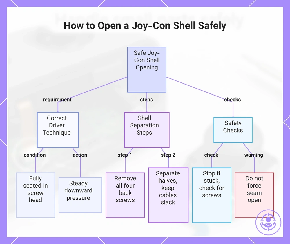
Opening the Joy-Con shell and exposing the joystick module area
Safe opening means removing the outer shell without stripping the screws or pulling on the internal cable. Use the correct driver, fully seated in each screw head, apply steady downward pressure, and separate the halves gently to avoid pulling on the internal cable.
- Insert the correct tri-point driver into each of the four back screws, keeping the driver fully seated to reduce the risk of stripped heads.
- Remove all four screws and set them aside.
- Starting at the rail edge, gently lift the back shell away from the front housing, using a plastic opening tool if the seam is tight.
- Support both halves of the housing as you separate them, keeping the internal cables slack.
- If the shell does not separate easily, stop and verify no screws remain attached; do not force the seam open.
- Once the back shell is free, rest it beside the controller without pulling on the antenna or battery ribbon.
When the joystick module area is visible and all internal cables are loose, the shell opening is complete and ready for the next disconnection step.
This chart shows the key requirements, steps, and safety checks for safely opening a Joy-Con shell to expose the joystick module.
Disconnecting and lifting out the original joystick module without stressing cables
Removing the original joystick module without stressing cables starts with releasing any securing latch on the flex-cable connector. Pulling on the cable or twisting the module can damage contacts, so release latch first.
These steps help avoid stressing the flex cable and keep nearby components clear.
- Identify whether the connector uses a latch or a friction fit. If a latch is present, gently flip it upward until it is fully released. Check that the latch is fully released and the flex cable can move freely.
- Support the flex cable near the connector with your non-dominant hand. Check that the cable lies flat without twisting or bending sharply.
- Grasp the connector body (not the cable) and apply a straight pull directly away from the board. Check that the pull is aligned with the connector axis to avoid bending the contacts.
- Once the connector is free, lift the module evenly out of its socket. Check that nearby components, such as capacitors or other connectors, are not touched during removal.
- Inspect the flex cable and connector after removal. Check that the contacts are straight and the cable shows no creases or tears.
- Set the module aside on a clean, static‑safe surface. Check that the cable is not trapped under the module or other parts.
Avoid stressing the cable by not twisting it sharply or pulling the module before the connector is released.
Joystick module alignment, seating, and screw-down order for a clean fit
Clean seating and correct cable routing directly affect input reliability after replacement. Alignment means the replacement joystick module sits flush against the board with no gaps under the frame, and mounting holes align naturally before screw insertion. When seated flat, the stick can move freely and the potentiometer can read accurately; the goal is a module that is flush and aligned.
Before securing the module, perform two checks to avoid issues after replacement.
- Alignment checks: verify the module sits flat without rocking, the mounting holes align, and the frame does not contact nearby components.
- Cable routing checks: ensure the cable path is clear, no wires are pinched or trapped under the module, and the ribbon or wires lay flat without folds.
If the module rocks or sits unevenly, re‑seat it flat before tightening. Follow the screw-down order, applying even pressure in a crossing pattern to prevent tilting. Re‑seat if it rocks.
Closing the shell with checkpoints before final screws go in
Checkpoints before final screws reduce the chance of reopening. Verify before final screws.
To avoid reopening, use these checkpoints:
- Cable clearance: ribbon cable moves freely with no obstruction.
- Latch locked: each latch clicks into its housing.
- Module flush: joystick sits evenly on mounting surface.
- Shell edges aligned: top and bottom halves meet without gaps.
- No wires pinched between the two shell halves.
- Battery connector seated: cable lies flat.
- Bumper and trigger buttons: move freely after closure.
- Screw posts: line up with their corresponding holes.
Stop if a cable is pinched; reopen and reroute before continuing.
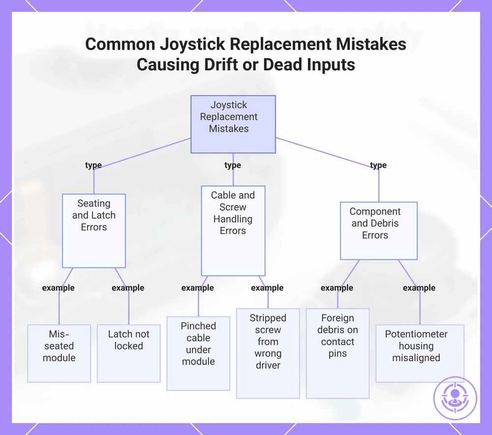
Common Joystick Replacement Mistakes That Create Drift-Like Behavior or Dead Inputs
Most post-replacement drift-like symptoms or dead inputs are caused by installation mistakes—usually improper seating, latch locking, cable routing, or screw handling—that produce erratic movement, unresponsive zones, or phantom inputs. Check installation mistakes first.
- Mis-seated joystick module can cause drift-like movement or no input at certain angles. Correct by reseating the module until it sits flat and the latch clicks.
- Latch not locked may lead to intermittent dead input or inconsistent response. Fix by pressing the latch firmly until it locks securely.
- Pinched cable under the module often results in erratic input or no response on one axis. Remove the module, reroute the cable without tension, and reinstall.
- Stripped screw from using the wrong driver can leave the module loose, causing drift-like behavior. Replace the screw and use the correct sized driver.
- Foreign debris on contact pins can cause sporadic drift or dead zones. Clean the pins with isopropyl alcohol and let dry before reassembly.
- Potentiometer housing misaligned during reassembly may produce inconsistent resistance readings and drift-like symptoms. Open the housing, align the carbon track correctly, and reassemble.
- Over-tightened screws distort the module, leading to stiff movement or unintended inputs. Loosen the screws slightly to relieve pressure.
- Using an incorrect replacement module variant can result in dead input or mismatched resistance. Verify the module part number matches the original before installation.
- Damaged ribbon cable during installation often leads to no response on one axis. Carefully unseat and reseat the cable; replace if bent or torn.
Re-check seating and latch locking after any correction. A drift-like issue only after reassembly is an installation problem, not recurrence; such symptoms often resolve by rerouting or reseating, while genuine drift needs further diagnosis. For no input at all, move to non-response checks such as verifying cable connections and screw tightness.
This chart categorizes common installation mistakes that cause drift-like behavior or dead inputs after joystick replacement, helping you identify the specific error.
Mis-seated module, unlocked latches, and pinched flex cables as the main repeat offenders
Three physical failure points commonly cause issues after reassembly: a mis-seated module, an unlocked latch, or a pinched flex cable. Check these three first before retesting.
Check and correct each offender:
- Mis-seated module: Check that the joystick module sits flush against the housing. If tilted or raised, reseat it until alignment pins seat fully and the module lies flat.
- Unlocked latch: Check that the flex cable latch is fully closed and locked. If open, relock by pressing the latch down until it clicks, ensuring the cable is seated beneath.
- Pinched flex cable: Check that the ribbon cable follows a clear path without being caught between housing halves or under screws. If pinched, reroute the cable with enough clearance and verify no tension.
After these checks, if the joystick still fails to register, stop testing and reopen the assembly for a full inspection instead of continuing with unresolved faults.
If the joystick is not responding after replacement
A joystick showing no input after replacement usually means a poor connection at the connector or a ribbon/flex cable not fully seated. The module itself is rarely faulty at this stage. Check connections first before further disassembly.
A structured check isolates the failure with minimal repeated disassembly. Start with the least invasive steps:
- Verify the connector latch is locked.
- Check that the ribbon cable is aligned and fully inserted.
- Ensure the module seat is flush.
This table isolates the most common causes of a no‑input condition after replacement:
| Symptom / Check | What to inspect | Pass looks like | If fail, do this |
|---|---|---|---|
| No input from one joystick | Connector latch on the motherboard | Latch is fully locked; ribbon cable cannot move | Open latch, re‑seat cable, lock latch again |
| No input from both joysticks | Ribbon/flex cable alignment | Contact pins are centered under the connector; cable is straight | Remove and re‑seat cable, ensuring straight insertion |
| No input after reassembly | Ribbon cable path (no pinching or bending) | Cable runs straight; no kinks or tears | Re‑route cable, avoid sharp bends, check for trapped wiring |
For example, if the left joystick gives no input while the right works, the left connector latch is often not fully locked. If all checks pass, proceed to testing and calibration after replacement to confirm full operation.
It is often assumed that a non‑responding joystick after replacement is automatically a defective module. In most cases, a simple connection or alignment fix resolves the issue. Only after all checks pass should a faulty module be considered, so don't force reassembly without verifying each check.
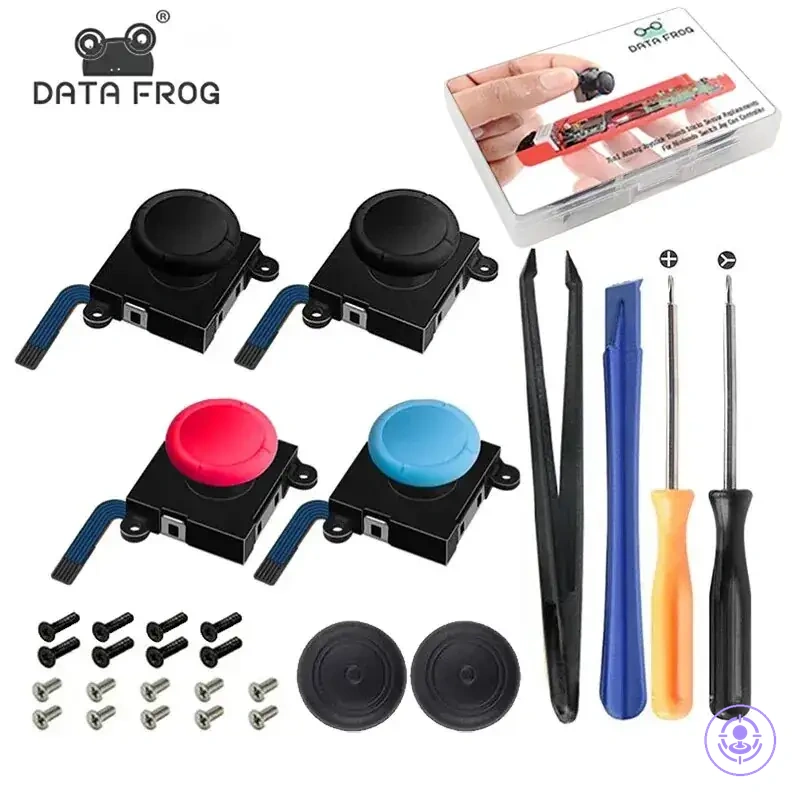
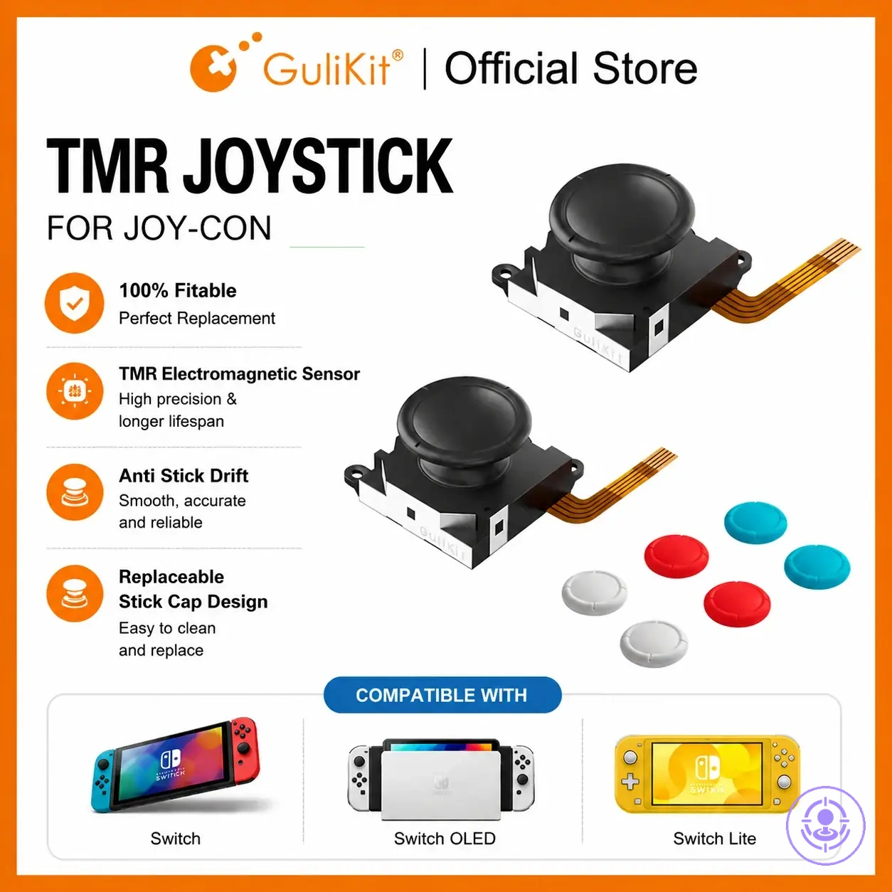
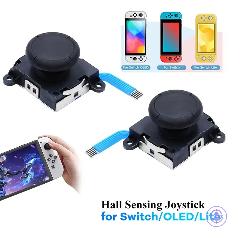
The products below are useful examples for comparing available options. Before buying, check that the compatibility criteria, key features, and product details match your needs.
Connection checks to do before moving on to calibration and full post-repair testing
Connection checks confirm that connection points are secure before calibration, so the system receives predictable input instead of intermittent signals from loose contacts. A loose latch or partially seated cable can mimic a component failure. Verify before calibration.
If a connection point fails repeatedly, reopen for inspection instead of repeating software-only attempts. Confirm each point before proceeding:
- Latch state: Connector clip fully locked. Pass: audible click, no visible gap.
- Insertion depth: Connector fully seated. Pass: connector body flush with housing, no space.
- Cable straightness: Ribbon cable straight, no sharp angles or pinches. Pass: lies flat without trapped sections.
- Alignment: Connector orientation matches socket guide. Pass: alignment arrows or notches line up without force.
- Seating pressure: Connector pressed evenly home. Pass: no tilt or raised edge along width.
Reopen if repeats.
Stop conditions that indicate a deeper issue and require broader troubleshooting steps
Stop conditions signal when repeated module replacement becomes unproductive. Recognizing them early protects parts by preventing unnecessary handling. When inspection reveals stop conditions, further replacement steps risk causing more harm, so stopping early protects the parts.
Differentiate between module replacement checks and broader troubleshooting: For example, a loose ribbon connection often causes intermittent response that resolves after reseating, while consistent failure across multiple new joystick modules suggests a deeper controller issue. The following stop conditions indicate when further replacement may cause more harm than benefit:
- Physical damage: Look for visible cracks, tears, or bent pins on the connector or ribbon. A damaged component suggests that reliable contact cannot be restored by simple replacement.
- Latch failure: Check that the connector latch clicks and holds securely. A broken latch suggests the new module may not seat correctly, leading to unreliable performance.
- Persistent non-response: If the controller shows repeated no input even after installing a fresh joystick, the problem likely extends beyond the joystick module to other internal components.
- Inconsistent input: Erratic cursor movement or drift that persists after replacement may indicate that calibration or signal processing is affected deeper in the system.
- Repeated failure within short time: A newly installed module that fails again quickly suggests environmental stress, power issues, or other underlying hardware problems.
- Unusual behavior across applications: If the issue occurs only in certain games or modes, software or driver factors may be at play rather than hardware alone.
For broader troubleshooting, refer to troubleshooting if issues remain.