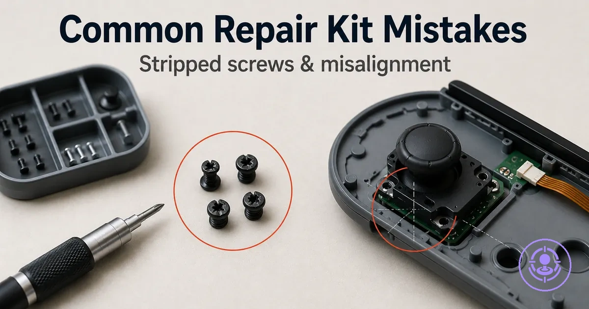
Joy-Con Drift Repair Kit Mistakes: How Stripped Screws, Misalignment, and Loose Connectors Happen
Joy-Con drift repair kit mistakes are the failure patterns that occur when a repair attempt goes wrong during disassembly or reassembly rather than from the drift itself. These errors involve three interconnected failure modes:
- a stripped screw often caused by improper bit fit or excessive torque
- a ribbon cable that may lose continuity if its connector latch is not fully seated
- mechanical misalignment that often results from uneven shell closure or a pinched flex cable
A Joy-Con that was functional before the repair may develop new problems after reassembly, such as intermittent response or a loose fit. This page covers mistake patterns rather than full repair steps, allowing you to identify which handling error likely led to a new symptom without retracing the entire joystick replacement workflow.
Outcomes depend on screw condition, latch fragility, and minor model variations, so the same action can produce different results across units. For a broader overview of repair workflows beyond the mistake patterns, refer to the Joy-Con drift repair kit hub.
What a repair kit mistake changes inside a Joy-Con
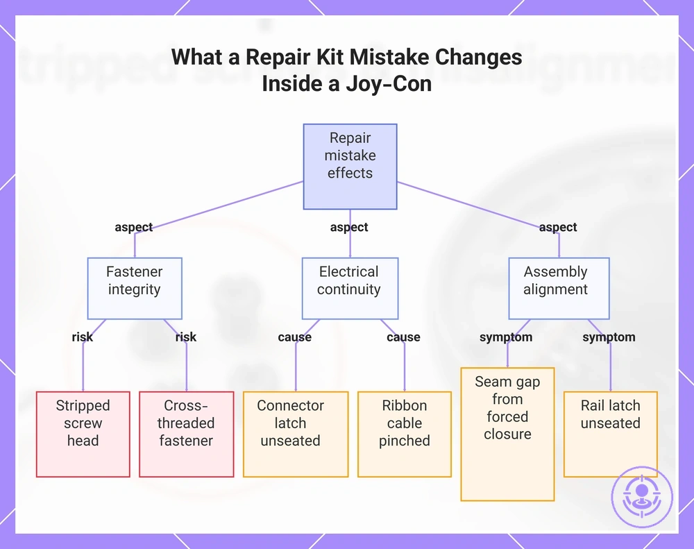
A repair kit mistake is a handling or assembly choice that changes the physical state of a fastener, connector, cable, or seating inside a Joy-Con. It may strip a screw head, unseat a ribbon latch, pinch a flex cable, or leave a shell seam misaligned. These four categories—fastener integrity, electrical continuity, mechanical alignment, and closure seating—cover the aspects a mistake can affect.
Reversible state error, such as a loose connector, can often be corrected by reseating. Physical damage, like a stripped thread, may require part replacement. Because model revisions vary, the same handling choice can produce different outcomes across Joy-Con versions. Any symptom that appears after a repair should be treated as a signal that a state change may have occurred, not as proof of a specific mistake.
- Fastener integrity: Over-torquing a screw head can strip the thread, making removal difficult. A cross-threaded fastener may not hold the shell together firmly.
- Electrical continuity: Improperly seating a connector latch or routing a ribbon cable across a sharp edge can break contact and cause intermittent or lost function.
- Mechanical alignment: Forcing the shell closed without aligning internal components can pinch a cable or increase resistance on moving parts, leading to a gap at the seam.
- Closure seating: Misaligning the back cover can leave the rail latch unseated, causing the Joy-Con to slide off the console without pressing the release button.
This chart shows the main categories of physical state changes a repair mistake can cause inside a Joy-Con, including fastener, electrical, and assembly issues.
Mistakes that block the repair result vs mistakes that physically damage parts
Repair mistakes that block the result are reversible, while mistakes that physically damage parts are typically irreversible. The criteria sort mistakes by reversibility and escalation risk, guiding whether to attempt recovery by rechecking the repair or stop and replace a damaged component.
| Outcome type | Typical mistake state | Safest first action | Escalation risk |
|---|---|---|---|
| Reversible (blocks repair result) | Incorrect reassembly or a loose connection that may prevent operation without damaging the part. | Reseat the component and recheck alignment and fit. | Low-risk; the repair can proceed once the error is corrected. |
| Irreversible (physically damages parts) | Over-tightening that can cause a torn or cracked component. | Stop further assembly immediately and replace the damaged part. | High risk; repeated attempts often make the damage worse. |
The most failure-prone touchpoints: screw heads, ribbon cables, connector latches, and shell seating
The most failure-prone touchpoints—screw heads, ribbon cables, connector latches, and shell seating—each have a fragile attribute that can fail when mishandled. These are the touchpoints you handle directly. The diagram labels where these failure-prone touchpoints appear: screw head locations, ribbon cable paths, connector latch zones, and the shell seating line.
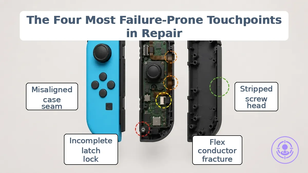
- Screw head: A mismatched bit fit often causes cam-out, which may strip the head. Stripping often makes removal difficult.
- Ribbon cable: Sharp bends or pinches can fracture the flex conductors. An intermittent connection is a common consequence.
- Connector latch: Failure to fully lock the latch may leave the cable partially seated. Missing function or loose contact often follows.
- Shell seating: Misaligned case seams create resistance during closure. A visible gap or warped housing is the typical result.
Preparation mistakes that create avoidable damage before opening the shell
Poor preparation and control cause most avoidable damage during repair, not complex electronics work. Rushing into disassembly without checking bit fit, work surface stability, or screw order often leads to stripped threads, pinched cables, or lost hardware. Control beats force.
A prep checklist to avoid errors prevents the preparation mistakes that cause stripped threads, pinched cables, and misalignment. Start by verifying that your bit profile matches the screw head size for full engagement.
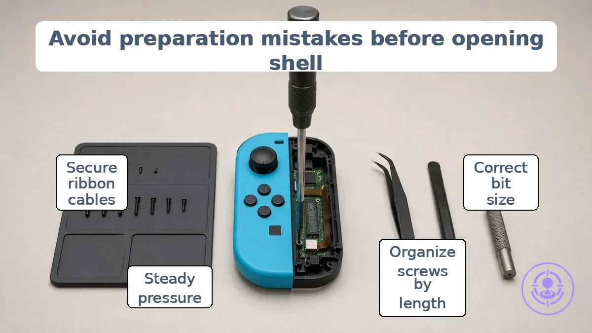
- Use the correct bit size and profile to prevent stripped screw heads.
- Organize screws by position and length to avoid mix-ups that cause misalignment.
- Work under adequate lighting and on a stable surface to reduce the chance of slipping.
- Hold the driver straight and apply steady pressure to prevent cam-out and edge damage.
- Keep a magnetic mat or labeled container nearby to prevent losing small parts.
- Avoid excessive force when the screw resists and check for cross-threading to prevent thread damage.
- Secure loose ribbon cables before rotating the board to prevent tearing.
Bit-to-screw fit errors that lead to instant stripping
Stripping often starts when the driver profile or size does not match the screw head, or when the bit does not achieve full engagement. Proper screwdrivers and screw handling are necessary to avoid the mismatches in this list. The mismatches show how these fit errors strip screw heads.
- Wrong driver profile (e.g., Phillips bit in a Pozidriv screw) → bit feels loose and slips under torque → cam-out occurs because the tapered flanks lose contact with the parallel drive walls.
- Incorrect bit size (e.g., #1 bit in a #2 recess) → wobble and poor contact → rounding of the recess edges as force concentrates on a small area.
- Worn or rounded bit tip → reduced surface contact → increased downward pressure needed to prevent slip, which accelerates cam-out and rounding.
- Partial engagement (bit not fully seated) → bit rests on the recess tips rather than the flanks → slip and deformation of the drive hole.
Screw control mistakes: mixing lengths, losing hardware, and over-torquing on reassembly
Mixed screws, lost hardware, and over-torquing commonly cause closure gaps, pressure issues, and misalignment after reassembly. Use this checklist to prevent mix-ups and misalignment by keeping attention on identification, placement consistency, and torque discipline.
- Before disassembly, label each screw group by its screw length and screw position to avoid a screw length mix-up during reassembly.
- Separate hardware by function so that a wrong hole placement does not create a standoff or gap under the shell.
- Check that each screw seats fully without resistance; if it binds, stop and verify the screw length and hole match.
- Avoid overtightening on plastic posts, as excessive force can crack the post or cause thread damage that prevents secure closure.
- Use a consistent tightening sequence and stop as soon as the screw is snug to reduce the risk of overtightening.
Handling mistakes that kink, crease, or snag ribbon cables
Ribbon cables often fail because of bending, snagging, or sharp-edge contact during handling. The motions listed below may cause kinks, creases, or snags that damage the cable.
- Bending the ribbon cable beyond its recommended bend radius may create a crease and cause intermittent or missing input.
- Pulling the ribbon cable against a sharp edge can pinch the conductors and increase tear risk.
- Snagging the ribbon cable during assembly can induce localized stress and internal damage.
- Folding the ribbon cable sharply at a single point creases the traces, which may break over time.
- Pinching the ribbon cable between housing parts or under screws can sever connections and cause intermittent or complete failure.
Stripped screws and stuck screws during disassembly
Repeated slipping of a stripped or stuck screw increases damage risk, so escalate gradually and use a stop rule. Proper screwdrivers and screw handling can help avoid stripping initially, but already stripped screws need a different approach. When slipping repeats, stop and reassess.
Stripped or stuck screws often develop early rounding that is easy to overlook. The annotated image highlights early stripping signs and correct driver bit seating to help avoid cam-out.
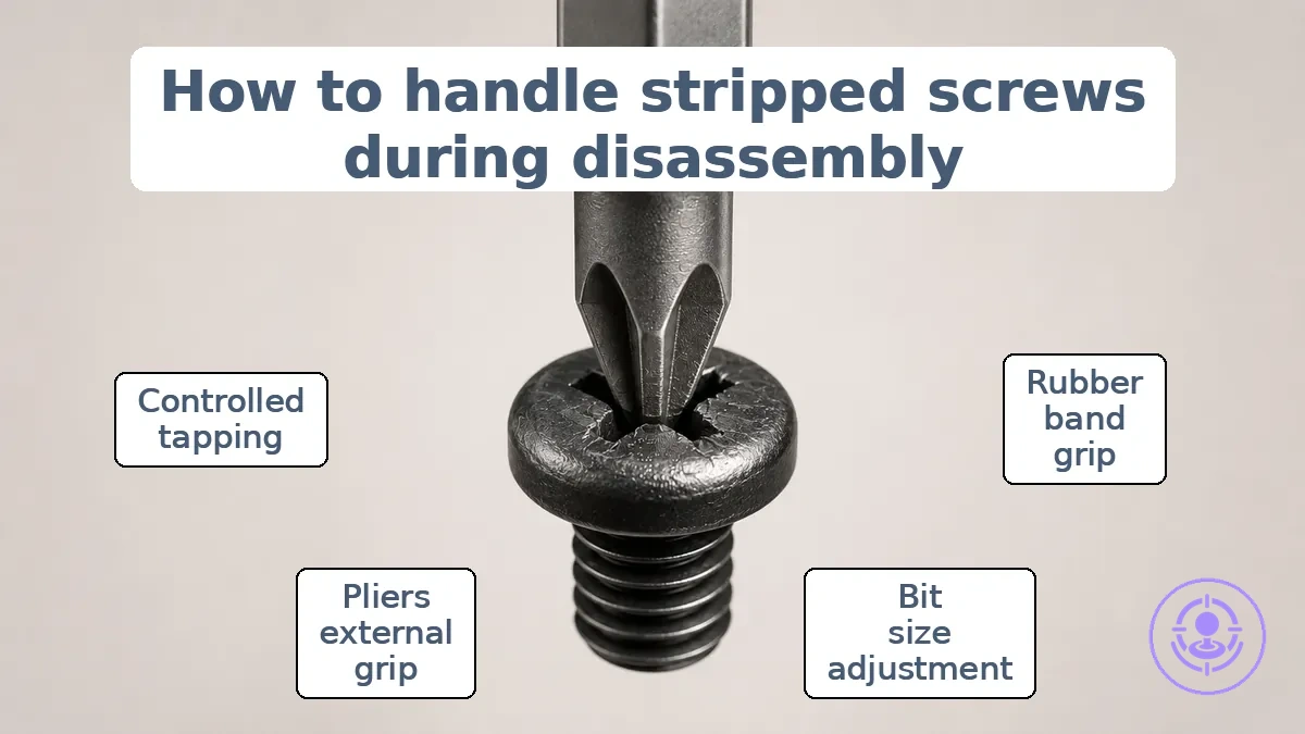
The steps below start with low-risk grip recovery and escalate only after a clear stop signal is triggered.
- Rubber band grip recovery. Place a wide rubber band over the stripped screw head, insert the driver bit, and apply firm downward pressure while turning slowly. Avoid tilting the driver, which worsens cam-out. Stop signal: If the driver still slips without any rotation, stop and move to the next step.
- Bit size and fit adjustment. Switch to a slightly larger driver bit or a different drive shape, such as a Torx bit, to engage undamaged metal inside the head. Avoid using a worn or undersized bit. Stop signal: If the new bit still cam-outs, do not force it.
- Pliers external grip. If the screw head is accessible above the surface, grip it with needle-nose or locking pliers and turn slowly. Avoid squeezing so hard that the head deforms. Stop signal: If the head begins to deform or the pliers slip, stop.
- Controlled lateral tapping. Lightly tap the screw head with a small hammer to break thread-bound friction or corrosion, then retry the rubber band or pliers method. Avoid heavy blows that can damage the housing. Stop signal: If the screw does not budge after tapping, do not continue.
The Earliest Signs a Screw Head is About to Strip
The earliest signs a screw head is about to strip are a slipping or wobbling driver, a grinding feel, and shiny edges or deformation on the recess. When you spot these cues, stop and realign before the head rounds out completely.
- Driver slips or wobbles during rotation instead of holding a steady bite — stop and realign.
- You feel a grinding or skipping sensation as torque is applied — stop and reassess.
- Shiny edges appear around the drive recess, often where the bit contacts the metal — stop and reassess.
- Rounding of the recess corners becomes visible at the contact points — stop and reassess.
- The driver no longer seats fully, requiring extra downward force to stay engaged — stop and realign.
- The edges appear flattened or the recess looks chewed — stop and reassess.
Common stripping causes: pressure angle, wrong driver profile, and cam-out behavior
Cam-out is a mechanical effect driven by mismatch and misalignment between the driver bit and screw recess—in short, a fit and angle problem.
Pressure angle, driver profile, and alignment affect force transfer. These cause-to-adjustment mappings link common stripping causes to safer adjustments.
- Wrong driver profile: Using a bit that does not match the screw recess shape reduces engagement and increases cam-out. Safer adjustment: Select the correct bit type and size before driving.
- Incorrect pressure angle: Tilting the driver relative to the screw axis changes the force vector, pushing the bit outward. Safer adjustment: Keep the driver aligned with the screw axis and apply steady, straight pressure.
- Worn or rounded bit: A dull or misshapen tip cannot engage fully, raising the likelihood of slip-out. Safer adjustment: Replace worn bits with sharp, matching bits that seat firmly in the recess.
- Misaligned engagement: Starting the driver off-center or at an angle prevents full surface contact. Safer adjustment: Ensure the bit is centered and fully seated before applying torque.
These adjustments can reduce cam-out and stripping risk, but they may not work on already damaged or overtightened screws, where additional care or alternative extraction methods are needed.
Controlled recovery attempts before escalation to extraction
A safe controlled recovery attempt restores screw head grip without enlarging head damage. Before extracting, low-risk attempts using steady alignment and traction may succeed if the screw head is not fully stripped. This step-by-step repair flow starts with the lowest-risk attempt and advances to more invasive techniques, each with a clear stop signal.
- Fit a bit that makes solid contact without wobble, apply firm downward pressure and turn slowly while maintaining alignment. If the bit slips, treat this as a stop signal and do not force it.
- Place a grip layer (such as a rubber band) between the bit and the screw head to increase traction. Re-seat the bit and attempt rotation with reduced slip; if the bit engages, continue; if not, stop.
- Apply penetrating oil to the screw head, wait briefly, then try again with steady pressure. If the screw does not move or the head deforms further, stop and consider extraction.
When a micro screw extractor helps and when it increases risk
Using a micro screw extractor is a last-resort option only when centered engagement with the screw head remains possible. Off-center drilling increases the risk of collateral damage, especially to plastic posts or threads. This checklist separates conditions where extraction helps from those where it increases risk.
- Use when: The screw head provides a centering surface and you can maintain a straight, centered alignment perpendicular to the screw axis during drilling.
- Use when: The surrounding material is metal or otherwise robust and can typically withstand torque without fracturing.
- Use when: Controlled drilling at low speed and reverse extraction are feasible without impact.
- Use when: The risk of collateral damage to adjacent components is low because the screw is isolated.
- Avoid when: The screw head is completely stripped, broken flush, or missing, leaving no centering guide.
- Avoid when: Centered alignment cannot be visually confirmed after the initial pilot hole.
- Avoid when: The screw is in a plastic post or thin housing that can crack under extractor torque.
- Avoid when: Off-center drilling is likely due to awkward access, limited visibility, or an unstable workpiece.
- Avoid when: Alignment cannot be maintained during drilling – stop and consider alternative methods to prevent further damage.
Loose connector and ribbon seating mistakes that cause missing functions
Missing functions after Joy-Con reassembly often result from a loose connector latch or a ribbon cable not fully seated. A partially seated ribbon often causes intermittent behavior or mimics a component failure. Check the ribbon seating first before assuming deeper damage; if reseating does not restore function, post-repair troubleshooting may be needed.
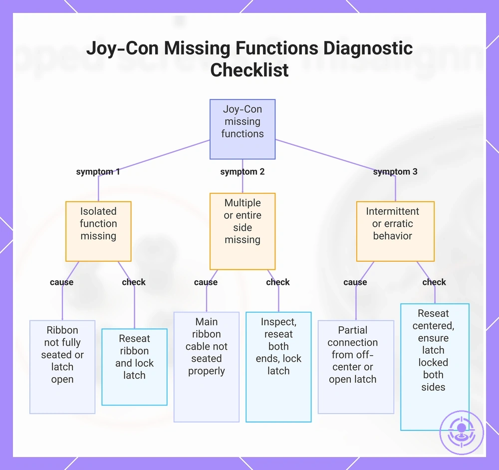
Partial seating is misleading: the connector may appear fully seated while the ribbon contacts only touch intermittently. Check each ribbon cable and connector latch in sequence, starting with the most common points of failure. This diagnostic checklist maps symptoms to common loose connector and ribbon seating mistakes and provides a safe reversible check for each.
- Missing function from a single button or trigger: likely cause is ribbon cable for that button not fully seated or the connector latch partially open. Check: Open the latch, reseat the ribbon until it stops, then lock the latch fully.
- Intermittent input from analog stick: likely cause is partial contact from a loose ribbon or a latch that did not click closed. Check: Remove the ribbon, inspect for bent contacts, reseat firmly, and ensure the latch is locked.
- No response from the entire controller side: likely cause is a main ribbon cable not seated at the motherboard connector or the latch not engaged. Check: Verify the ribbon is inserted straight and the latch is pressed down until it clicks.
- Erratic behavior or ghost inputs: likely cause is a partial connection from a ribbon that is slightly off-center or the latch not fully secured. Check: Reseat the ribbon, making sure it is centered and the latch is locked on both sides.
- LED or rumble not working: likely cause is the ribbon cable for that sub‑assembly not fully inserted or the latch not locked. Check: Open the connector, push the ribbon in until it stops, then close the latch completely.
- Multiple functions missing together: likely cause is the main ribbon cable connecting the daughterboard to the mainboard not seated properly. Check: Carefully remove the ribbon, inspect for damage, reseat, and lock the latch on both ends.
- Intermittent function that improves when pressing on the back of the controller: likely cause is a ribbon cable that is partially seated and makes better contact under pressure. Check: Open the connector, reseat the ribbon fully, and ensure the latch is locked.
This chart maps common ribbon seating mistakes to symptoms and provides reversible checks for each.
Connector Latch Mistakes: Not Fully Locked, Misaligned Insertion, and Latch Damage
A connector latch must be fully locked and properly aligned for reliable electrical continuity. The following connector latch mistakes map handling errors to their risks:
- Not fully locked: partial engagement may allow terminal back-out under vibration, causing intermittent signal loss.
- Misaligned insertion: forcing the connector at an angle can bend pins or damage the latch housing, leading to unreliable contact.
- Latch damage: a cracked or broken latch cannot reliably secure the connection, making accidental disconnection and intermittent continuity more likely.
- Partial lock: when the latch clicks but is not fully seated, micro-movement at the contact interface can increase resistance and cause intermittent faults.
- Over-tightening or prying: applying excessive force to the latch tab can deform the locking mechanism, reducing its ability to hold the connector securely.
Ribbon Routing Mistakes That Pinch Cables During Closure
Ribbon routing can pinch cables during closure when the cable crosses sharp edges, passes near screw posts, or runs through areas with moving parts. These errors can trap the cable between surfaces, creating resistance that prevents closure or damages the ribbon.
Before closing the assembly, use these clearance checks to catch routing mistakes that pinch:
- Check if the ribbon path clears any sharp enclosure edges that could catch or cut the cable during closure.
- Verify no cable is trapped under or around screw posts, as a trapped cable can create a closure gap.
- Ensure the cable does not pass through hinge lines or other moving parts that may pinch it when the assembly is closed.
- Confirm there is enough slack along the routing path to avoid tension that pulls the cable against an edge.
- Test for intermittent connection by gently pressing on the cable after closure; edge pinch often causes intermittent signals that can be resolved by reseating.
- If resistance is felt when closing the assembly, stop and inspect the path for any point where the cable is caught.
Post-reassembly symptoms that often indicate a loose connection
After reassembly, symptom clusters that often indicate a loose connection include intermittent electrical behavior, starting difficulties, and visible heat or damage—often from poor contact at terminals or ground points.
The table maps each symptom cluster to a safe first check, and further steps are covered under post-repair troubleshooting.
| Symptom cluster | Likely connection area | Safe check | What it usually means |
|---|---|---|---|
| Intermittent lights or devices cutting out | Battery terminals, connector pins, or ground points | Gently wiggle the suspected connector while the system is active and watch for the symptom to flicker. | A temporary break in contact often indicates a loose terminal or corroded pin that may need cleaning or reseating. |
| Engine cranks but does not start, or slow cranking | Battery cables, main ground strap, or starter circuit connectors | Inspect cable ends for tightness and corrosion; clean and reseat if needed. Do not force or overtighten. | High resistance at a loose battery cable can reduce current to the starter. If visible corrosion or damage is present, replace the terminal rather than reuse it. |
| Burning smell or melted plastic near connectors | Power-carrying connectors, fuse box, or high-current junctions | Touch the connector housing carefully. If it feels hot, stop operation immediately and do not restart until the connection is inspected. | Arcing from a loose connection generates heat that can melt plastic and create visible damage. This is a stop condition that requires replacement of the connector or terminal. |
Misalignment Mistakes That Prevent Closure or Create New Stress Points
When a shell won't close, closure resistance usually signals a mis-seated component or trapped cable rather than a need for more force.
Misalignment during reassembly can create pinch points that stress cables and components, leading to new symptoms like intermittent function or a visible gap along the shell seam. Before tightening screws, a quick diagnostic check can help prevent secondary damage.
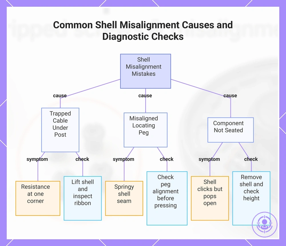
Each resistance cue maps to a likely blocker and a safe check:
- Resistance at one corner — Likely a trapped cable under a post. Safe check: lift the shell slightly and look for a compressed ribbon cable.
- Even gap won't close — Likely a pinch point on a ribbon cable. Safe check: verify the cable sits flat in its designated channel.
- Shell seam feels springy — Likely misalignment of a locating peg or post. Safe check: check peg alignment before pressing down.
- Shell clicks but pops open — Likely a component not fully seated in its socket. Safe check: remove the shell and check component height.
- One side closes, other side has a gap — Likely shell misalignment relative to the internal frame. Safe check: loosen all screws, align the seam evenly, then retighten gradually.
- Screw hole does not align — Likely an internal component shifted during assembly. Safe check: realign the component stack before screwing.
- Resistance after tightening screws — Likely a trapped cable or misaligned shell created by overtightening. Safe check: back out the screws and check for cable pinch or misaligned pegs.
- Shell warps when closed — Likely a misplaced cable creating a bulge. Safe check: confirm all cables run along the molded channels without crossing screw posts.
If resistance persists after these checks, stop and re‑inspect the assembly order and component seating.
This chart shows three common misalignment causes, their symptoms, and the safe checks to prevent secondary damage during reassembly.
Module seating mistakes that keep the shell from aligning
For module seating, each unit must sit flush so that screw holes and shell edges align naturally. Visible cues that a seating mistake is keeping the shell from aligning include:
- A tilt at the seam where one module sits higher than the adjacent unit.
- A visible gap between modules that widens toward the front or back edge.
- Resistance when inserting screws, suggesting the holes may no longer be aligned.
- A shifted module that does not sit square to the frame or adjacent piece.
- Uneven pressure on the shell when you try to close it, often felt as a bind or catch.
Common pinch points that cause misalignment: cables, foam pads, and battery placement
Pinch points are predictable traps that prevent full closure and can damage soft parts. When a cable, foam pad, or battery gets caught in a seam gap during reassembly, it creates resistance and may cause an intermittent or incomplete seal.
Common pinch points are organized by part type and location. Each entry notes the trapped part, closure symptom, and safe reseat action.
- Trapped cable in a seam gap: A cable caught in a seam gap can prevent full housing closure and may cause intermittent function. To reseat, lift the cable clear of the gap and reroute it along its intended channel.
- Foam pad mis-seat: A foam pad that is compressed or shifted out of position can create closure resistance and push the housing apart. Carefully reposition the pad so it sits flat without overlapping adjacent components.
- Battery placement pinch: A battery placed off-center can become trapped between the housing halves, causing uneven pressure and a visible seam gap. Remove the battery and reseat it centered within its cradle before closing.
- Ribbon cable at hinge: A ribbon cable caught near a hinge pivot can be pinched as the housing closes, leading to a hard stop or resistance. Verify the cable is routed away from the hinge before final closure.
- Wire harness between components: A wire bundle trapped between two internal parts can create a bulge that prevents the housing from seating flush. Tuck the harness into its designated slot and verify clearance.
- Foam pad on connector: A foam pad that overlaps a connector may prevent the connector from seating fully, which can cause functional issues. Trim or reposition the pad so it does not interfere with any connectors.
Forcing the case shut and the damage patterns it creates
Forcing closure often turns misalignment into cracked posts, pinched ribbons, or warped seating when the case is pressed shut without checking and correcting alignment first. Each damage pattern below is linked to its likely cause and the symptom risk it can create.
- Cracked post → alignment force concentrated on a single mounting post → loose or uneven case fit after reassembly
- Pinched ribbon → pressing shut traps a flex cable against the housing → new symptom like intermittent button response
- Warped seating → uneven pressure bends a plastic ledge or rail → possible permanent gap or difficulty reseating the case
- Scratched internal surface → sliding a misaligned shell past a sharp edge → cosmetic or grounding issues
- Stripped screw boss → forcing the screw while the case is already stressed → stripped thread and loose screw that fails to hold
Reassembly and verification mistakes that make drift seem “unfixed”
A verification mistake can make drift appear unfixed after reassembly, creating a false negative. Incomplete seating or misalignment may mask the repair effect. Verify before redoing.
Verification at this stage checks that the repair parts are seated correctly, the reassembly sequence was followed, and the joystick responds predictably before reopening the controller. For a deeper look, refer to post-repair troubleshooting.
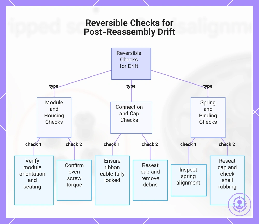
The following checklist prioritizes reversible checks that help avoid verification mistakes by confirming proper reassembly without reopening the case.
- Behavior: Drift persists exactly as before. Check: Verify replacement module orientation and seating. Interpretation: A misaligned module can mimic the original symptom.
- Behavior: Drift is present but weaker. Check: Confirm all screws are torqued evenly. Interpretation: Uneven screw pressure can warp the housing and affect the stick.
- Behavior: No response in one direction. Check: Ensure ribbon cable is fully inserted and locked. Interpretation: A loose connection can appear as a drift symptom.
- Behavior: Stick feels gritty. Check: Reseat the joystick cap and remove debris. Interpretation: Grittiness can be mistaken for stick drift when centered.
- Behavior: Center position drifts slowly. Check: Inspect spring alignment. Interpretation: A misplaced spring can cause drift that seems unrelated to repair.
- Behavior: Drift appears only in certain games. Check: Reseat the joystick cap and verify it does not rub against the shell. Interpretation: Physical binding can make drift seem game-specific, masking a proper repair.
This chart categorizes the six reversible checks listed in the section into three groups, helping you identify and fix verification mistakes without reopening the controller.
Skipping functional checks that reveal a bad seating or misalignment early
Run these minimum checks before final tightening to catch seating and alignment faults early. Performing them while reopening is still low-risk reveals issues sooner. Skipping them delays detection until after tightening, making correction more time-consuming.
- Press the part gently into its recess. Expected response: it sits flush without rocking. Deviation: the part tilts or shifts. Likely mistake: forcing the part instead of realigning it.
- Insert a screw by hand before using a driver. Expected response: the screw threads smoothly from the start. Deviation: the screw catches or does not advance. Likely mistake: cross-threading from initial misalignment.
- Slide or pivot the component manually through its range. Expected response: smooth motion with no obstruction. Deviation: movement is stiff, uneven, or stops suddenly. Likely mistake: a cable is pinched or the component is not fully seated.
- Check gap uniformity around the assembled edges. Expected response: even spacing on all sides. Deviation: gaps are wider on one side. Likely mistake: the component is installed crooked.
- Gently shake the assembly and listen. Expected response: no internal sounds. Deviation: a rattle or click indicates a loose part. Likely mistake: a clip or latch not fully locked.
- Tug lightly on each connector after insertion. Expected response: the connector holds and sits flush. Deviation: it pulls out easily or sits proud. Likely mistake: incomplete insertion due to a misaligned pin.
- Press the center of the seated part. Expected response: minimal flex, firm feel. Deviation: the part bows or deflects noticeably. Likely mistake: standoffs or supports are misaligned.
Contamination mistakes introduced during repair that can affect joystick behavior
Contamination mistakes during repair—such as introducing dust, residue, or oils—can affect joystick feel and consistency. Common contamination sources, along with their effects and simple prevention measures, include:
- Dust from a dirty workspace: can accumulate on internal tracks and cause feel inconsistency; prevention: clean the work area before starting the repair.
- Oils and sweat from unwashed hands: can transfer to contact surfaces and create smudges that interfere with smooth motion; prevention: wash hands or use gloves.
- Debris from worn components: can introduce grit that disrupts joystick feel and consistency; prevention: inspect and gently clean replacement parts before installation.
- Fabric fibers from cloths or clothing: can lodge in crevices and impede joystick travel; prevention: use lint-free cleaning materials.
Stop Conditions and Damage Containment When Something Goes Wrong
Stopping at the right time prevents compounding damage and preserves recoverability. When a repair step starts showing resistance or deformation, continuing often worsens the problem.
Damaged components or misaligned parts signal an active stop condition. Containment means limiting harm by halting the current action and reassessing the approach.
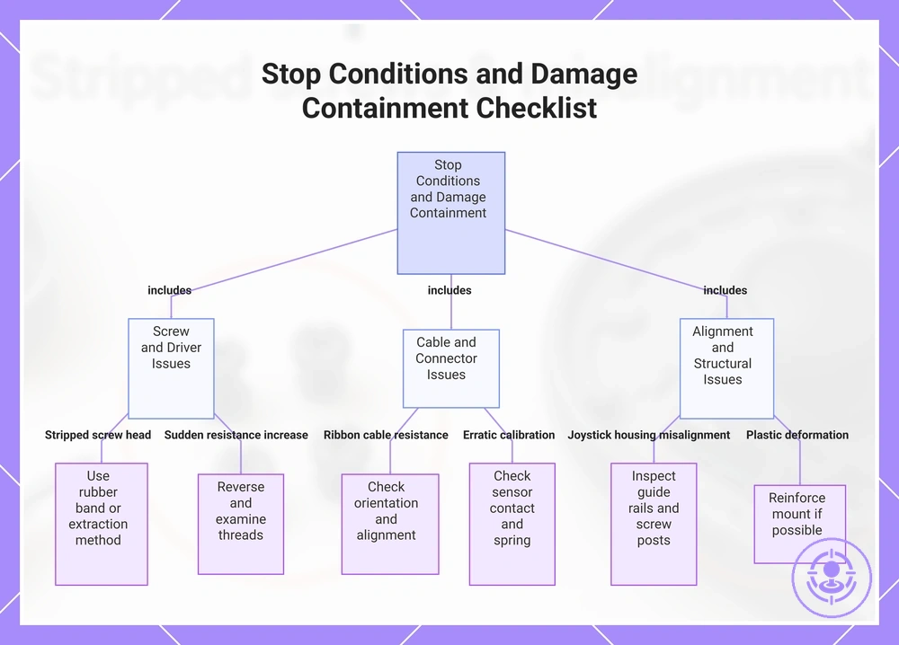
This stop-conditions and damage-containment checklist sets practical thresholds for common warning signals. A separate prep checklist to avoid errors can help establish those limits.
- Stripped screw head: Screw head becomes deformed or the bit slips repeatedly. – Stop immediately and use a rubber band or extraction method. – Avoid applying more torque or switching to a larger bit without inspection.
- Ribbon cable resistance: Cable resists insertion or folds at the connector. – Stop and remove the cable; check orientation and alignment of the connector. – Avoid pushing the cable further, which can tear traces.
- Joystick housing misalignment: Housing will not seat flush against the shell. – Stop and lift the module to inspect the guide rails and screw posts. – Avoid pressing down with force, which can crack mounting points.
- Sudden resistance increase: A screw becomes much harder to turn halfway. – Stop and reverse the screw to examine the threads. – Avoid using an electric driver at high speed, which can strip the thread.
- Plastic deformation: Stress marks or bending appear on internal mounts. – Stop and remove the affected component; reinforce the mount if possible. – Avoid repeating the same assembly angle, which worsens the stress.
- Erratic calibration after reassembly: Joystick registers movement when untouched. – Stop and disassemble to check the sensor contact and spring alignment. – Avoid relying on software calibration alone, as it may mask a physical misalignment.
- Repeated driver slip (cam-out): Screwdriver tip loses grip on the screw head multiple times. – Stop and switch to a manual driver with a better-fitting bit. – Avoid using a worn bit or increasing downward force.
This chart groups common repair warning signals into three categories and shows the immediate action to stop and contain damage.
How to decide when to stop to prevent irreversible screw, latch, or cable damage
Repeated slipping, visible deformation, or abnormal resistance are practical stop thresholds—continuing past them risks worsening damage instead of repairing it. The list below separates reversible resistance from progressive damage and helps you decide when to reassess your approach.
- Screw head repeatedly slips and rounds: Stop and switch to a larger or sharper bit, or use a screw extractor.
- Latch deformation or binding: Do not force; stop and reassess alignment to avoid permanent damage.
- Abnormal resistance during cable insertion: Stop to avoid pinching or insulation damage; inspect the cable path and realign.
- Screw spins without gripping: Indicates stripped thread; stop and use a larger screw or thread insert.
- Fastener requires excessive torque: Stop; over-torquing risks deformation or breakage; reassess lubrication or alignment.
- Cable kinks under tension: Do not force; reroute or relieve strain at the termination point.
- Screw head deforms under driver: Stop; switch to a manual tool or larger driver to avoid further stripping.
- Bit repeatedly cams out: Stop before the head rounds completely; try a different bit type or apply penetrating lubricant, then reassess.
If a ribbon tears or a latch breaks: safe next steps without expanding into a full repair guide
When a ribbon tears or a latch breaks, the safe next step is containment and assessment, not forcing reconnection. Forcing the part can turn a simple issue into recurring intermittent faults. These do/don't points outline immediate containment actions.
If the damage is contained, you can proceed to post-repair troubleshooting.
Caution: Do not attempt a full repair or replacement until the damage is properly assessed.
Do now
- Stop using the controller immediately to prevent further tearing of the ribbon.
- Visually assess the ribbon for tears, creases, or tangles.
- Check the latch area for debris or misalignment that may prevent proper closure.
- Stabilize the torn ribbon by gently re-aligning the ends if possible, without applying tension.
Do not do
- Force the ribbon latch closed if it resists; doing so can damage contacts and cause intermittent faults.
- Continue using the controller with a visibly torn ribbon — this can embed debris and worsen the damage.
- Pull or tug on a stuck ribbon; this can stretch or tear the material further.
- Assume the damage is benign without inspection — even minor tears can lead to intermittent faults.